logo
Home ProductsOther

General Electric DS200SHVIG1B Auxiliary Interface Panel

General Electric DS200SHVIG1B Auxiliary Interface Panel

  • General Electric DS200SHVIG1B Auxiliary Interface Panel
  • General Electric DS200SHVIG1B Auxiliary Interface Panel
  • General Electric DS200SHVIG1B Auxiliary Interface Panel
General Electric DS200SHVIG1B Auxiliary Interface Panel
Product Details:
Place of Origin: America
Brand Name: GE
Certification: CE
Model Number: DS200SHVIG1B
Payment & Shipping Terms:
Minimum Order Quantity: 1
Price: Negotiation
Packaging Details: Carton
Delivery Time: 3-5 Work Days
Payment Terms: T/T
Supply Ability: 1
Contact Now
Detailed Product Description
Highlight:

DS200SHVIG1B Interface Panel

,

DS200SHVIG1B Auxiliary Interface Panel

,

General Electric Auxiliary Interface Panel

Product Description:DS200SHVIG1B

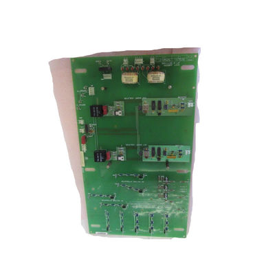
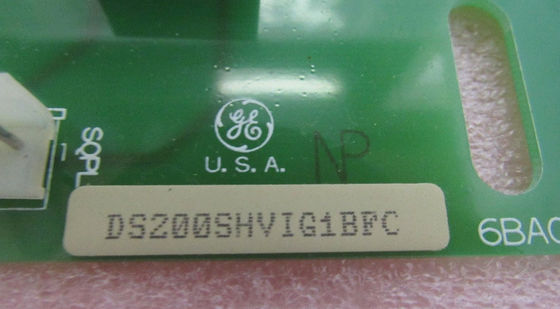
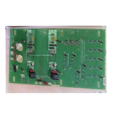
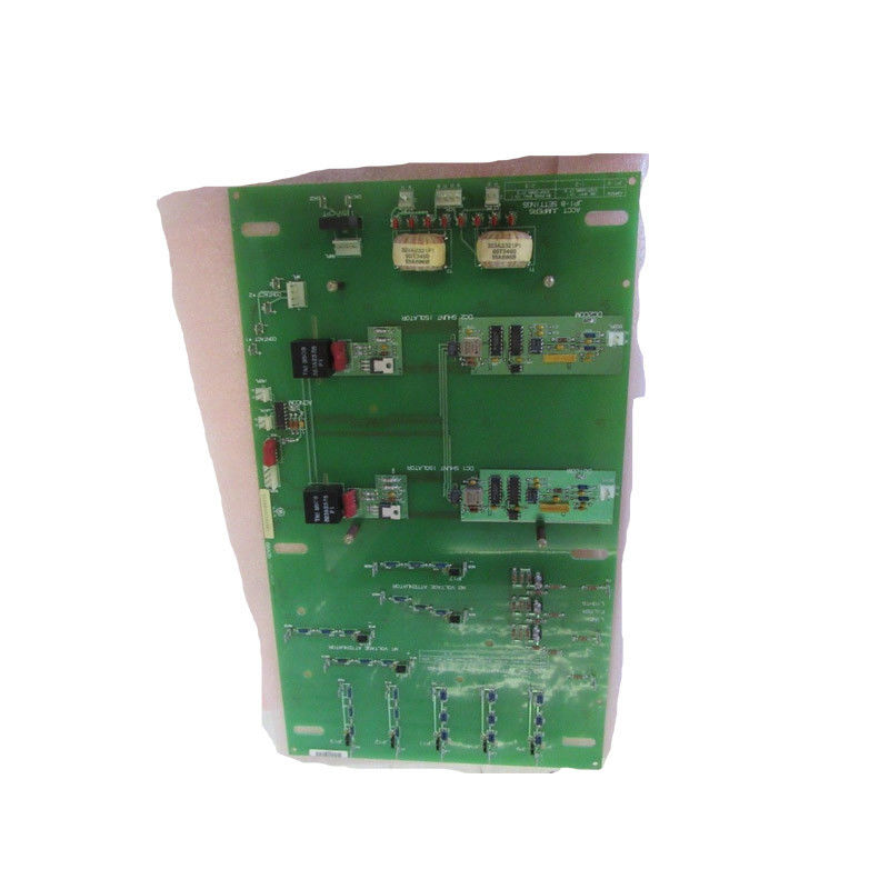
  • The DS200SHVIG1B is a part of GE's Mark V board series. It serves as a crucial component in the GE Excitation EX2000 gas - turbine control system. As a SCR (Silicon - Controlled Rectifier) high - voltage interface board, it acts as an intermediary between the input voltage signals and the driver's power supply. This function is vital for the proper operation of the overall control system as it enables the conversion and transmission of voltage signals in a specific range (- 500mV to 500mV) and then transforms them into a differential frequency from 0 to 500kHz. The driver's power supply can then respond based on this converted frequency, facilitating the control and regulation of the associated equipment.
 

Features:DS200SHVIG1B

    • Series Affiliation and System Role
      • The DS200SHVIG1B is a part of GE's Mark V board series. It serves as a crucial component in the GE Excitation EX2000 gas - turbine control system. As a SCR (Silicon - Controlled Rectifier) high - voltage interface board, it acts as an intermediary between the input voltage signals and the driver's power supply. This function is vital for the proper operation of the overall control system as it enables the conversion and transmission of voltage signals in a specific range (- 500mV to 500mV) and then transforms them into a differential frequency from 0 to 500kHz. The driver's power supply can then respond based on this converted frequency, facilitating the control and regulation of the associated equipment.
  • Physical and Configuration Features
    • Jumper Configuration and Protection
      • The board is equipped with 17 configurable jumpers. These jumpers play a significant role in adding extra attenuation capabilities to the board. Attenuation is important for adjusting the strength or amplitude of the signals passing through the board. The jumpers are protected by 10:1 current transformers. This protection mechanism safeguards the jumpers and the overall circuit from excessive current, ensuring the reliable operation of the board's configuration settings. In case of any issues such as a blown filter fuse on the board, there are three on - board LED indicators. These LEDs act as an alert system, providing users with a quick visual indication of potential problems, allowing for prompt troubleshooting and maintenance.
    • Compatibility and Installation
      • One of the notable features of the DS200SHVIG1B is its compatibility. It is designed to be easily installed into a wide range of GE - branded drives. This ease of installation makes it a versatile component that can interface with various types of drives and exciters. Whether it's different models of gas - turbine drives or other equipment requiring high - voltage interfacing, the DS200SHVIG1B can provide the necessary connection and signal - conversion functions.
    • Reliability and Handling Precautions
      • The board is generally reliable, but its performance can be affected by improper handling and storage. To maintain its integrity, it is recommended to store the board in an anti - static storage box. Electrostatic discharge (ESD) can damage the sensitive electronic components on the board. Therefore, following ESD - safe precautions during handling, such as using anti - static wrist straps and working on an anti - static mat, is crucial to ensure the long - term functionality and reliability of the DS200SHVIG1B.
  • Technical Specifications Details
    • I/O (Input/Output) Points
      • The board has a total of 32 digital input points and 32 digital output points. These I/O points serve as the connection points for various external devices and the control system. The digital inputs can receive signals from sensors, switches, or other monitoring devices, while the digital outputs can send control signals to actuators, relays, or other components that affect the operation of the equipment.
    • Input and Output Voltage Ranges
      • For the digital inputs, the voltage range is from 0 - 24VDC (Direct Current) or 0 - 120VAC (Alternating Current). This wide range of input voltage options allows the board to interface with different types of input devices that may operate at different voltage levels. The digital output voltage range is also from 0 - 24VDC or 0 - 120VAC, enabling it to provide appropriate output signals to a variety of output - driven devices.
    • Response Times
      • The input response time of the board is 5ms, which indicates how quickly the board can recognize and process an incoming input signal. The output response time is 1ms, showing the speed at which the board can generate and send an output signal after receiving an appropriate input or internal command. These response times are important factors in determining the overall speed and efficiency of the control system in which the board is used.
    • Operating Temperature Range
      • The DS200SHVIG1B has an operating temperature range from - 40°C to 85°C. This wide temperature range allows the board to function in various environmental conditions, whether it's in a cold outdoor installation or a hot industrial environment. The ability to operate within such a broad temperature range is essential for its use in different industrial applications without the risk of performance degradation due to temperature - related issues.
    • Communication Interface
      • The board communicates with the Mark V control system through a VMEbus interface. The VMEbus interface provides a reliable and standardized means of data transfer and communication between the DS200SHVIG1B and the rest of the control system. This enables the seamless integration of the high - voltage interface board into the overall control architecture, allowing for efficient sharing of data and control signals.
 

Technical Parameters:DS200SHVIG1B

    • Jumper Configuration Options
      • The 17 configurable jumpers are a standout feature. They provide users with the ability to customize the board's attenuation characteristics. Attenuation is essential for adapting the board to different signal - strength requirements and for fine - tuning the input - output characteristics. For example, in a system where the input signals have a wide range of amplitudes, the jumpers can be configured to ensure that the signals are appropriately attenuated to a level that the board can process accurately. The protection of these jumpers by 10:1 current transformers adds an extra layer of reliability, safeguarding the configuration settings from electrical faults and current surges.
    • Fault - Indication LEDs
      • The three on - board LED indicators for fuse - blown alerts are a user - friendly feature. In a complex industrial control system, quickly identifying the source of a problem is crucial. These LEDs provide an immediate visual cue when a filter fuse on the board blows. This allows maintenance personnel to quickly locate and address the issue, minimizing downtime and ensuring the continued operation of the equipment.
      •  

Applications:DS200SHVIG1B

    • Digital Input
      • Number of Points: The DS200SHVIG1B has 32 digital input points. These multiple input points allow for a wide range of sensors and control signals to be connected to the board. For example, in a turbine - control system, these points can be used to receive signals from temperature sensors, pressure sensors, and position - indicating switches.
      • Voltage Range: The input voltage range for digital inputs is 0 - 24VDC (Direct Current) or 0 - 120VAC (Alternating Current). This broad voltage range provides flexibility in interfacing with different types of input devices. Some sensors may operate at a lower DC voltage, while others, such as certain types of proximity switches, may provide an AC voltage signal. The ability to handle both DC and AC voltages within these ranges ensures compatibility with a wide variety of industrial - control - system components.
      • Response Time: The input response time is 5ms. This parameter defines how quickly the board can detect and process an incoming input signal. In a high - speed control system, a relatively short response time like this is crucial for timely decision - making and accurate control. For instance, in a system that requires rapid response to changes in temperature or pressure, a 5ms response time allows the control system to quickly adjust the operation of the equipment based on the new sensor readings.
    • Digital Output
      • Number of Points: There are 32 digital output points. These output points can be used to control a diverse range of actuators and indicator devices. For example, they can drive relays to control the power supply to motors or solenoids to operate valves. The large number of output points provides the ability to manage multiple components simultaneously, enabling complex control strategies.
      • Voltage Range: The output voltage range for digital outputs is 0 - 24VDC or 0 - 120VAC. Similar to the input voltage range, this allows the board to interface with a wide variety of output - driven devices. Some actuators may require a lower DC voltage for operation, while others, such as some types of industrial lights, may operate at a higher AC voltage.
      • Response Time: The output response time is 1ms. This short response time is beneficial for quickly actuating the controlled devices. For example, when a control signal is sent to a solenoid - operated valve to adjust the flow of a fluid in a process - control system, the 1ms response time ensures a rapid response, minimizing the lag between the control decision and the actual adjustment of the valve.
  1. Signal - Conversion Parameters
    • Input Signal Voltage Range
      • The board can handle an input voltage signal range of - 500mV to 500mV. This range is important for accepting different levels of voltage signals from sensors or other signal - generating sources. For example, in a system that measures small electrical - potential differences, such as in some types of electrochemical sensors, the ability to handle this voltage range allows the board to accurately capture and convert these signals.
      • Output Signal Frequency Range
      • It converts the input voltage signals into a differential frequency ranging from 0 to 500kHz. This frequency - conversion process is a key aspect of the board's function. The differential frequency output provides a standardized way to transmit the information to the driver's power supply. The 0 - 500kHz range allows for a wide range of frequencies to be used for encoding different signal magnitudes or states, enabling precise control and communication with the power - supply component.
  2. Environmental and Physical Parameters
    • Operating Temperature
      • The operating temperature range of the DS200SHVIG1B is from - 40°C to 85°C. This wide temperature range is a significant advantage in industrial applications. It means that the board can function properly in both cold and hot environments. In cold - weather applications, such as in outdoor power - generation facilities in cold regions, the board can withstand low temperatures without malfunctioning. In hot industrial settings, like in factories where equipment generates a lot of heat, it can also operate effectively up to 85°C.
    • Communication Interface
      • The board uses a VMEbus interface for communication with the Mark V control system. The VMEbus is a well - established and reliable communication standard. It typically provides high - speed data transfer and a defined protocol for communication. The use of this interface allows for seamless integration of the DS200SHVIG1B into the Mark V control - system architecture. The specific characteristics of the VMEbus interface, such as data - transfer rates, address - mapping, and bus - arbitration methods, are determined by the VMEbus standard and can vary depending on the implementation and the requirements of the overall control system.
 

Customization:DS200SHVIG1B

    • Attenuation Adjustment
      • The 17 configurable jumpers on the DS200SHVIG1B provide a significant opportunity for customization. Attenuation can be adjusted using these jumpers to fine - tune the input signal strength. For example, in a system where the input voltage signals have a wide range of amplitudes, the jumpers can be set to attenuate stronger signals to a level that the board's input circuitry can handle more effectively. This allows for better signal - to - noise ratio and more accurate processing of the input signals. The attenuation can also be adjusted according to the specific requirements of different sensors or input devices. For instance, if a particular sensor provides a relatively high - voltage output, the jumpers can be configured to reduce the signal amplitude to match the optimal input range of the board.
    • Signal - Processing Customization
      • The jumpers can also be used to customize other aspects of signal processing. Depending on the application, the frequency - conversion characteristics might need to be adjusted. By changing the jumper settings, users can potentially modify the way the input voltage signals are converted into the differential frequency output. This could involve adjusting the gain or offset in the conversion process to optimize the output signal for the specific requirements of the driver's power supply. For example, in a system where the power supply responds more effectively to a certain range of frequencies, the jumpers can be used to customize the conversion to produce frequencies within that preferred range.
  1. Communication - Interface Customization
    • VMEbus Configuration
      • The VMEbus interface offers some level of customization. Users can configure the VMEbus settings such as the data - transfer rate and the address - mapping according to the requirements of the overall control system. The data - transfer rate can be adjusted to match the speed of other components in the system. For example, if the Mark V control system and other connected devices have a high - speed data - transfer capability, the VMEbus interface on the DS200SHVIG1B can be configured to operate at a higher data - transfer rate to ensure efficient and timely communication. The address - mapping customization allows for the unique identification of the board within the VMEbus - connected system, enabling proper communication and data - sharing between different components.
    • Protocol - Specific Customization
      • Depending on the specific requirements of the application and the Mark V control system, users can customize the communication protocol used over the VMEbus. While the VMEbus has its own standard protocol, there may be room for customization in terms of how the board interacts with other components. For example, users can define specific data - packet formats or communication sequences to optimize the exchange of control commands and status updates. This could involve customizing the way error - handling and re - transmission of data are implemented to ensure reliable communication in a noisy or high - traffic industrial - control - system environment.
  2. Digital I/O Customization
    • Input - Signal Customization
      • The 32 digital input points can be customized in terms of the types of input signals they accept. Based on the available voltage range (0 - 24VDC or 0 - 120VAC), users can select or design input circuits to interface with different sensors and switches. For example, if a particular application requires a more sensitive input for a specific type of sensor, a custom input circuit can be designed to amplify or condition the input signal to make it more suitable for the digital - input range of the board. Additionally, the input - response - time parameter of 5ms can be considered when customizing the input circuits. In applications where faster response times are desired, additional circuitry can be added to reduce the effective input - response time, such as using pre - amplification or signal - buffering techniques.
    • Output - Signal Customization
      • The 32 digital output points can be customized to control different types of output - driven devices. Based on the output - voltage range (0 - 24VDC or 0 - 120VAC), users can select appropriate actuators or indicator devices. For example, for applications that require precise control of small DC motors, the digital - output points can be configured to provide the appropriate voltage and current levels. The output - response - time of 1ms can also be optimized through custom circuitry. In applications where very fast actuation is needed, such as in high - speed valve - control systems, additional components can be added to reduce the overall response time and ensure rapid activation of the controlled devices.
 

Support and Services:DS200SHVIG1B

Our Product Technical Support team is available to assist you with any technical issues or questions that you may have regarding the Other product. Our knowledgeable technicians can provide help with installation, setup, troubleshooting, and more. We also offer a variety of services to help you get the most out of your product, including training sessions, product demonstrations, and customization options.

Contact Details
Wisdomlong Technology CO.,LTD

Contact Person: Florence Zhang

Tel: 86-18318060200

Fax: Zhang hefei

Send your inquiry directly to us (0 / 3000)

Other Products