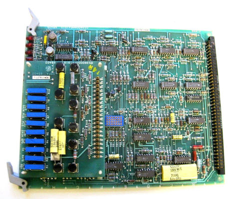
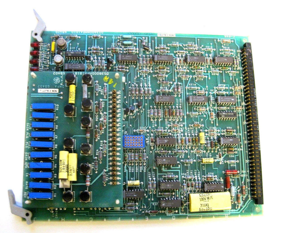
- Input Voltage Range:
- It likely has a defined range of acceptable input voltages to power its internal circuits. This could be something like 110 - 240 VAC (alternating current) for compatibility with standard industrial power supplies. Some models might also support a DC (direct current) input voltage range, perhaps in the order of 24 - 48 VDC depending on its design and the power source available in the industrial system. The voltage tolerance around these nominal values would typically be specified to account for minor fluctuations in the power source.
- For example, it might have a tolerance of ±10% around the nominal AC voltage, meaning it can operate reliably within a range of approximately 99 - 264 VAC.
- Input Current Rating:
- There would be an input current rating that indicates the maximum amount of current the device can draw under normal operating conditions. This is crucial for sizing the appropriate power supply and circuit protection devices. Depending on its power consumption and internal circuitry complexity, it might have an input current rating of a few amperes, say 1 - 5 A for typical applications. However, in systems with higher power requirements or when multiple components are powered simultaneously, this rating could be higher.
- Input Frequency (if applicable):
- If designed for AC input, it would operate with a specific input frequency, usually either 50 Hz or 60 Hz depending on the region's power grid standard. Some advanced models might be able to handle a wider frequency range or have the ability to adapt to different frequencies within certain limits to accommodate variations in power sources or specific application needs.
- Output Voltage Range for Magnetic Field Control:
- The DS3800DMFA controls the magnetic field by adjusting the voltage supplied to relevant windings or components. The output voltage range for this purpose would vary depending on the type and rating of the motors or generators it's designed to work with. It could span from a few volts to several hundred volts. For instance, it might be able to provide an adjustable output voltage in the range of 0 - 500 VDC for exciting the magnetic field windings of a medium-sized motor or generator.
- Output Current Capacity:
- There would be a defined maximum output current that the control board can supply to the magnetic field control circuit. This determines its ability to drive the necessary magnetic field in the electrical machine. The output current capacity could range from a few amperes for smaller motors or generators to tens or even hundreds of amperes for larger industrial units, depending on the application. For example, in a large industrial motor used for heavy-duty applications like steel rolling mills, it might need to supply a high current to create a strong magnetic field.
- Power Output Capacity:
- The maximum power output that the board can deliver to the magnetic field control circuit would be specified. This is calculated by multiplying the output voltage and current and gives an indication of its ability to handle different equipment sizes and load requirements. It could range from a few hundred watts for low-power applications to several kilowatts for larger motors or generators. For example, in a small servo motor application, the power output might be in the range of a few hundred watts, while for a large industrial generator excitation system, it could be several kilowatts.
- Control Resolution:
- In terms of its control over the magnetic field, it would have a certain level of control resolution for adjusting parameters like voltage or current. For example, it might be able to adjust the magnetic field excitation voltage in increments as fine as 0.1 V or have a percentage-based control resolution of ±0.1% for more precise applications. This high level of precision enables accurate regulation of the magnetic field strength and, consequently, the performance of the electrical machine it controls.
- Signal-to-Noise Ratio (SNR):
- When handling input signals from sensors (such as voltage and current sensors) or generating output signals for the magnetic field control circuit, it would have an SNR specification. A higher SNR indicates better signal quality and the ability to accurately process and distinguish the desired signals from background noise. This could be expressed in decibels (dB), with typical values depending on the application but aiming for a relatively high SNR to ensure reliable signal processing. In a noisy industrial environment with multiple electrical devices operating nearby, a good SNR is essential for accurate control.
- Sampling Rate:
- For analog-to-digital conversion of input signals (if applicable) and for monitoring various electrical parameters, there would be a defined sampling rate. This is the number of samples it takes per second of the analog signal. It could range from a few hundred samples per second for slower-changing signals to several thousand samples per second for more dynamic signals, depending on the nature of the sensors and the control requirements. For example, when monitoring rapidly changing current in a motor winding during startup or under load variations, a higher sampling rate would be beneficial for capturing accurate data.
- Supported Protocols:
- It likely supports various communication protocols to interact with other devices in the industrial system and for integration with control and monitoring systems. This could include standard industrial protocols like Modbus (both RTU and TCP/IP variants), Ethernet/IP, and potentially GE's own proprietary protocols. The specific version and features of each protocol that it implements would be detailed, including aspects like the maximum data transfer rate for each protocol, the number of supported connections, and any specific configuration options available for integration with other devices.
- Communication Interface:
- The DS3800DMFA would have physical communication interfaces, which could include Ethernet ports (perhaps supporting standards like 10/100/1000BASE-T), serial ports (like RS-232 or RS-485 for Modbus RTU), or other specialized interfaces depending on the protocols it supports. The pin configurations, cabling requirements, and maximum cable lengths for reliable communication over these interfaces would also be specified. For example, an RS-485 serial port might have a maximum cable length of several thousand feet under certain baud rate conditions for reliable data transmission in a large industrial facility.
- Data Transfer Rate:
- There would be defined maximum data transfer rates for sending and receiving data over its communication interfaces. For Ethernet-based communication, it could support speeds up to 1 Gbps (gigabit per second) or a portion of that depending on the actual implementation and the connected network infrastructure. For serial communication, baud rates like 9600, 19200, 38400 bps (bits per second), etc., would be available options. The chosen data transfer rate would depend on factors such as the amount of data to be exchanged, the communication distance, and the response time requirements of the system.
- Operating Temperature Range:
- It would have a specified operating temperature range within which it can function reliably. Given its application in industrial environments that can experience significant temperature variations, this range might be something like -20°C to +60°C or a similar range that covers both the cooler areas within an industrial plant and the heat generated by operating equipment. In some extreme industrial settings like outdoor mining operations or desert-based power plants, a wider temperature range might be required.
- Storage Temperature Range:
- A separate storage temperature range would be defined for when the device is not in use. This range is usually wider than the operating temperature range to account for less controlled storage conditions, such as in a warehouse. It could be something like -40°C to +80°C to accommodate various storage environments.
- Humidity Range:
- There would be an acceptable relative humidity range, typically around 10% - 90% relative humidity (without condensation). Humidity can affect the electrical insulation and performance of electronic components, so this range ensures proper functioning in different moisture conditions. In environments with high humidity, like in some coastal industrial plants, proper ventilation and protection against moisture ingress are important to maintain the device's performance.
- Protection Level:
- It might have an IP (Ingress Protection) rating that indicates its ability to protect against dust and water ingress. For example, an IP20 rating would mean it can prevent the ingress of solid objects larger than 12mm and is protected against water splashes from any direction. Higher IP ratings would offer more protection in harsher environments. In dusty manufacturing facilities or those with occasional water exposure, a higher IP rating might be preferred.
- Dimensions:
- The physical size of the DS3800DMFA would be specified in terms of length, width, and height, usually measured in millimeters or inches. These dimensions are important for determining how it can be installed within an equipment rack or enclosure in an industrial setup. For example, it might have dimensions of 10 inches by 8 inches by 2 inches to fit into a standard 19-inch industrial equipment rack with appropriate mounting brackets.
- Weight:
- The weight of the device would also be provided, which is relevant for installation considerations, especially when it comes to ensuring proper mounting and support to handle its mass. A heavier control board might require sturdier mounting hardware and careful installation to prevent damage or misalignment.
- Connectors:
- It has specific types of connectors for its input and output connections. For example, it might have screw terminals for electrical connections, which can accommodate wires of a certain gauge range. There could also be ribbon cable connectors, such as a 20-pin or 34-pin ribbon cable connector for interfacing with other components in the system. The pinout and electrical specifications of these connectors would be clearly defined. For instance, a 20-pin ribbon cable connector might have specific pin assignments for power, ground, input signals, and output control signals.
- Resistors and Jumpers:
- As mentioned previously, it is populated with a certain number of adjustable resistors and jumpers. The resistors would have specific resistance ranges (e.g., from a few ohms to several kilohms) that can be adjusted to fine-tune control parameters. The jumpers would be designed with specific configurations and positions to enable/disable functions or change signal paths, and their electrical characteristics and usage instructions would be detailed. For example, a jumper might be used to switch between different control modes or to connect/disconnect a specific sensor input to the control circuit.
|

 Your message must be between 20-3,000 characters!
 Please check your E-mail!
  Your message must be between 20-3,000 characters!
 Please check your E-mail!

