Product Description:DS3800NADB
- Board Dimensions and Structure
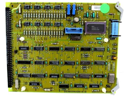
- As a printed circuit board, the DS3800NADB has a relatively large footprint, which is designed to accommodate a variety of components. The board's size is optimized to house all the necessary circuitry for its analog - to - digital conversion functions. The presence of drilled holes at the upper - right and lower - right corners indicates a standard mounting mechanism. These holes are likely designed to fit into a specific enclosure or control panel within the industrial system, ensuring a secure and stable installation. This is crucial in environments where vibrations from machinery, such as those in a power plant, could potentially disrupt the card's operation if not properly mounted.
- Component Layout
- Integrated Circuits: The board is populated with a significant number of integrated circuits. These ICs play diverse roles in the analog - to - digital conversion process. For example, some may be dedicated to signal amplification, ensuring that weak analog input signals are boosted to a suitable level for accurate conversion. Others could be involved in the actual analog - to - digital conversion operation, using complex algorithms to precisely digitize the analog signals. The strategic placement of these ICs on the board is designed to minimize signal interference and optimize the overall conversion efficiency.
- Resistors and Capacitors: There is an array of resistors and capacitors on the DS3800NADB. Resistors are used to control the flow of electric current, set voltage levels, and perform functions like impedance matching. Capacitors, on the other hand, are employed for tasks such as filtering out electrical noise, decoupling power supplies, and storing and releasing electrical charge as required. Their combination helps in conditioning the analog input signals, making them more suitable for the analog - to - digital conversion process.
- Connectors: The board is equipped with male and female connectors. These connectors are essential for establishing communication with other components within the industrial control system. The male connector can be used to send out digital signals that have been converted from analog inputs, while the female connector may be used to receive power, control signals, or additional analog input signals. The design of these connectors ensures a reliable and secure connection, minimizing the risk of signal loss or electrical shorts.
- Analog - to - Digital Conversion
- High - Resolution Conversion: As a 12 - bit analog - to - digital conversion card, the DS3800NADB offers a high level of resolution in converting analog signals to digital form. A 12 - bit resolution means that it can distinguish between 4096 different levels within the input analog signal range. This high resolution is crucial in applications where precise measurement and control are required, such as in turbine control systems. For instance, in a gas turbine, accurate conversion of analog signals from sensors measuring parameters like temperature, pressure, and flow rate is essential for maintaining optimal turbine performance.
- Input Signal Handling: The card is designed to handle a variety of analog input signals. It can accept signals from different types of sensors, such as thermocouples for temperature measurement, pressure transducers, and flow meters. These analog signals can have different voltage ranges, and the DS3800NADB is likely equipped with input circuitry that can scale and condition these signals to be within the appropriate range for the analog - to - digital conversion process.
- Data Output and Communication
- Digital Output Format: Once the analog signals are converted into digital form, the DS3800NADB outputs the data in a format that can be easily processed by other components in the system. The digital output may be in a parallel or serial format, depending on the design requirements. This digital data can then be sent to microcontrollers, programmable logic controllers (PLCs), or other digital processing units within the turbine control system. These units can use the digital data to make decisions, such as adjusting the fuel flow rate, turbine speed, or blade angles to ensure efficient and safe operation of the turbine.
- Communication with Other Components: The male and female connectors on the board enable seamless communication with other components in the industrial control system. The card can communicate with other boards that are responsible for tasks like data storage, display, or further signal processing. For example, it can send the converted digital data to a display board, which can then present the information to operators in a human - readable format. Additionally, it can receive control signals from a central control unit, which may adjust the card's operation, such as changing the input signal range or the conversion rate.
- Temperature and Humidity Resistance
- The DS3800NADB is designed to operate within a specific temperature range, typically suitable for industrial environments. In power plants or other industrial settings, the temperature can vary significantly, and the card is engineered to withstand these fluctuations without compromising its performance. Similarly, it can handle a certain range of humidity levels, ensuring reliable operation even in humid conditions. This environmental adaptability is achieved through the use of components that are rated for these conditions and appropriate thermal management and moisture - resistant design features on the board.
- Electromagnetic Compatibility (EMC)
- Industrial environments are often filled with electromagnetic interference (EMI) from various sources, such as motors, transformers, and radio - frequency (RF) transmitters. The DS3800NADB is designed to be electromagnetically compatible, meaning it can operate without being significantly affected by these external electromagnetic fields. It likely has built - in shielding and filtering mechanisms to protect its internal components from EMI and RFI. This ensures that the analog - to - digital conversion process remains accurate, and the data output is reliable, even in the presence of strong electromagnetic noise.
Features:DS3800NADB
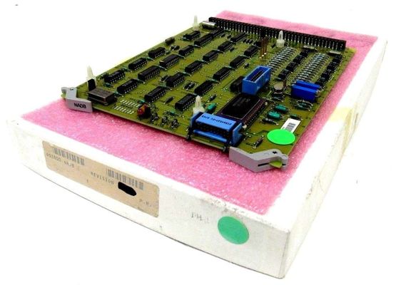
- Board Structure: It is a relatively large printed circuit board and functions as a motherboard to the smaller auxiliary board DS3800DADB. It has an extractor tab attached to its upper and lower right corners for easy extraction and installation. The board is factory drilled and marked for alignment on the bottom edge with "NADB 6 DA 02 6 BA 04".
- Connectors: It has one male connector, one female connector, and one ribbon connector for communicating with the DS3800DADB. The connectors ensure reliable connections with other components in the system.
- Components
- LED Indicator: It has one amber LED marked "P OK" to indicate the power status or the normal operation of the board.
- Test Points: There are three TP test points marked COM/SYNC/AOUT, which can be used for testing and debugging purposes.
- Resistors and Capacitors: It has two variable resistor potentiometers and multiple capacitors. The capacitors play a role in filtering and energy storage, while the potentiometers can be adjusted to fine-tune certain parameters.
- Integrated Circuits: It is populated with multiple integrated circuits, including the ADC85H-12 12-bit A/D converter with reference and clock. The design of this chip includes scaling resistors that provide analog input signal ranges of ±2.5, ±5, ±10, 0 to +5, or 0 to +10 volts.
Jumper Switches: It has multiple jumper switches. J1 is marked "range", J2 is marked "parity" and can be set to in or out, and J3 is marked "osc" and can be set to in or out, allowing for some customization and configuration of the board's operation.
Spare PTH: There are spare plated through-holes located along its right edge, providing the possibility for additional circuit modifications or expansions if needed.
High Resolution: As a 12-bit analog-to-digital conversion card, it can distinguish between 4096 different levels within the input analog signal range, providing high-precision conversion for accurate measurement and control.
Output Signal Compatibility: All digital signals are DTL and TTL compatible, and the data output is negative-true and available in either serial or parallel form, making it easy to interface with other digital devices in the system.
Redundancy Design: The GE Speedtronic Mark IV system, of which the DS3800NADB is a part, has integrated chipsets with two-out-of-three voting redundancies on all protection parameters and critical controls, enhancing the reliability and safety of the system.
Technical Parameters:DS3800NADB
- Resolution: 12 bits, which means it can distinguish between 4096 different levels within the input analog signal range, providing high-precision conversion for accurate measurement and control.
- Input Signal Range: The ADC85H-12 12-bit A/D converter on the board has scaling resistors that provide analog input signal ranges of ±2.5, ±5, ±10, 0 to +5, or 0 to +10 volts.
- Compatibility: All digital signals are DTL and TTL compatible, and the data output is negative-true.
- Output Format: The data output is available in either serial or parallel form, making it easy to interface with other digital devices in the system.
- Male Connector: Located on one short edge of the board, used to send out digital signals or connect to other components that require the converted digital data.
- Female Connector: Populates the other short edge, which may be used to receive power, control signals, or additional analog input signals.
- Ribbon Connector: Used for communicating with the DS3800DADB auxiliary board.
- Voltage: The specific voltage requirements are not publicly available in detail, but it is designed to operate within the power supply range provided by the GE Speedtronic Mark IV system.
- Power Consumption: The power consumption of the board is not specified in the public domain, but it is optimized to operate efficiently within the turbine control system environment.
- LED Indicator: It has one amber LED marked "P OK" to indicate the power status or the normal operation of the board.
- Test Points: There are three TP test points marked COM/SYNC/AOUT, which can be used for testing and debugging purposes.
- Resistors and Capacitors: It has two variable resistor potentiometers and multiple capacitors. The capacitors play a role in filtering and energy storage, while the potentiometers can be adjusted to fine-tune certain parameters.
- Jumper Switches: J1 is marked "range", J2 is marked "parity" and can be set to in or out, and J3 is marked "osc" and can be set to in or out, allowing for some customization and configuration of the board's operation.
- Spare PTH: There are spare plated through-holes located along its right edge, providing the possibility for additional circuit modifications or expansions if needed.
Applications:DS3800NADB
As a key component of the GE Speedtronic Mark IV system, which is designed for gas and steam turbine control, the DS3800NADB is used to convert analog signals from various sensors in the turbine system, such as temperature, pressure, and vibration sensors, into digital signals. The digital signals can then be processed and analyzed by the control system to monitor the operating status of the turbine, make accurate control decisions, and ensure the safe and efficient operation of the turbine. For example, in a power plant, it helps to control the steam turbine's speed, output power, and temperature to maintain stable power generation.
- Process Control: In industrial production processes such as chemical, oil refining, and food processing, the DS3800NADB can be used to convert analog signals from process variables such as flow rate, level, and concentration into digital signals for the programmable logic controller (PLC) or distributed control system (DCS) to process and control. This enables precise regulation of the production process, ensuring product quality and production efficiency.
- Robotics: In robotic systems, the DS3800NADB can be used to convert analog signals from sensors such as force sensors, position sensors, and vision sensors into digital signals for the robot controller to process and analyze. This allows the robot to accurately perceive the external environment and perform tasks such as grasping, assembly, and welding with high precision.
In equipment monitoring and diagnostic systems, the DS3800NADB can be used to convert analog signals from sensors on the equipment into digital signals for further analysis and processing. By continuously monitoring the equipment's operating status and analyzing the data, potential faults and problems can be detected in a timely manner, and predictive maintenance can be carried out to reduce equipment downtime and maintenance costs. For example, in a manufacturing plant, it can monitor the vibration and temperature of key equipment to predict possible failures and take preventive measures.
In research and development laboratories, the DS3800NADB can be used in experimental setups to convert analog signals from sensors and instruments into digital signals for data acquisition and analysis. It can be used in experiments related to physics, chemistry, biology, and other fields to accurately measure and record experimental data, providing a basis for scientific research and technological innovation. For example, in a materials science laboratory, it can be used to measure the electrical and mechanical properties of materials.
Customization:DS3800NADB
- Interaction with the DS3800DADB Auxiliary Board: The DS3800NADB serves as the main board and connects to the DS3800DADB auxiliary board via a ribbon cable. The eight 708a1 200v m/e capacitors on the auxiliary board can significantly increase the capacitance of the DS3800NADB, thus optimizing the overall system performance.
- Integration within the Speedtronic Mark IV System: It is part of the GE Speedtronic Mark IV system, working in tandem with other control boards, sensors, and actuators in the system. Together, they achieve precise control over gas and steam turbines. For instance, it shares data and control signals with other control boards to ensure the coordinated operation of the entire system.
- Fault Detection: The amber "P OK" LED indicator on the board can be observed to preliminarily determine whether the power supply or the board's operating status is normal. Additionally, the three TP test points marked COM/SYNC/AOUT enable technicians to conduct more in - depth signal detection and fault - finding.
- Repair and Replacement: Since the GE DS3800NADB is a key component in the GE Speedtronic Mark IV system, professional technicians are generally recommended for repair and replacement. During the repair process, professional testing equipment and tools such as oscilloscopes and multimeters are required to ensure the quality and safety of the repair. Some specialized industrial automation repair companies or GE's after - sales service centers can provide relevant repair services.
- Technological Upgrades: With the continuous development of electronic technology, A/D conversion technology is also evolving. Higher - resolution, higher - conversion - speed, and lower - power - consumption A/D conversion chips are emerging. However, due to the widespread use of the GE Speedtronic Mark IV system in some specific fields, the DS3800NADB remains an essential component for now. In the future, it may gradually be replaced by products with better performance.
- Compatibility and Upgrades: When considering upgrading or replacing the GE DS3800NADB, full consideration must be given to its compatibility with the existing system. New replacement products need to be compatible with the original system in terms of electrical performance, interface specifications, and functions to ensure the normal operation of the system. At the same time, a comprehensive evaluation and testing of the system are required to avoid compatibility issues and potential safety hazards.
- J1: Marked "range", which can be adjusted to change the analog input signal range. The ADC85H-12 12-bit A/D converter on the board has scaling resistors that provide analog input signal ranges of ±2.5, ±5, ±10, 0 to +5, or 0 to +10 volts.
- J2: Marked "parity", which can be set to "in" or "out", allowing for the configuration of parity settings for data transmission. This is useful in ensuring the accuracy and integrity of data communication between the board and other devices.
- J3: Marked "osc", and can be set to "in" or "out", enabling the customization of the oscillator settings. This can be adjusted according to the specific requirements of the system to optimize the board's operation frequency and stability.
-
There are spare plated through-holes located along the right edge of the board. These provide the possibility for additional circuit modifications or expansions. Users can add custom components, such as resistors, capacitors, or other integrated circuits, to the board to meet specific application requirements or to implement additional functionality.
Support and Services:DS3800NADB
Our product technical support team is available to assist you with any questions or issues you may have regarding your product. We offer a range of services including troubleshooting, repair, and maintenance. Our team is highly trained and knowledgeable about our products, and we are committed to providing you with the best possible support experience.
In addition to technical support, we also offer a variety of services to help you get the most out of your product. These services include product training, installation, and customization. Our team will work with you to develop a tailored solution that meets your specific needs and requirements.
We understand that every customer is unique, and we strive to provide personalized support and services to ensure your satisfaction. Our goal is to help you achieve maximum productivity and efficiency with your product, and we are dedicated to helping you succeed.

 Your message must be between 20-3,000 characters!