Place of Origin: | Singapore |
Brand Name: | ROSEMOUNT |
Certification: | Does not supply |
Model Number: | 3051CFADL060DCHPS2T100032AA1 |
Minimum Order Quantity: | 1 ea |
---|---|
Price: | Negotiate |
Packaging Details: | Does not supply |
Delivery Time: | 8 WEEKS |
Payment Terms: | T/T,PAYONEER |
Supply Ability: | 20EA,6-8weeks |
BRAND: | EMERSON ROSEMOUNT | MODEL: | 3051CFADL060DCHPS2T100032AA1 |
---|---|---|---|
CATEGORY: | Annubar Flow Meter | SUPPLY: | NOS |
Measurement Type: | Differential Pressure | Delivery Time: | 8 Weeks |
High Light: | 3051CFADL060DCHPS2T100032AA1 Pressure Temperature Transmitter 50mm,50mm Pressure Temperature Transmitter,Annubar Flow Meter Differential Pressure |
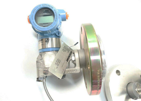
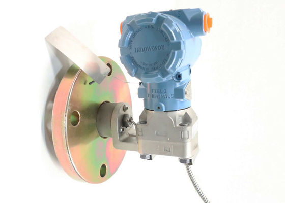
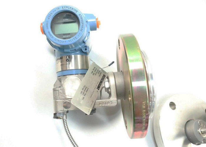
3051CFADL060DCHPS2T100032AA1 Annubar Flow Meter Differential pressure
Product Information Of : 3051CFADL060DCHPS2T100032AA1
Brand | EMERSON ROSEMOUNT |
Model | 3051CFADL060DCHPS2T100032AA1 |
SUPPLY |
6-in |
SIZE | No |
Weight | Does not supply |
The Rosemount 3051CFA Annubar Flow Meter uses the T-shaped sensor design that delivers best in class accuracy and performance while meeting the needs of diverse process applications, whether it is high accuracy for precision control or high strength for severe flow applications. Main capabilities include:
■Up to 1.8 percent of flow rate accuracy.
■Available in 2- to 96-in. (50 to 2400 mm) line.
■Fully assembled and leak tested for out-of-the-box installation.
■The Loop Integrity Diagnostic continuously monitors the electrical loop to detect changes that compromise the integrity of the transmitted 4-20 mA output signal (Option Code DA0).
■LOI with straightforward menus and built-in configuration buttons (option code M4).
More options :
3051CG3A02A1AB1H2L4M5K5
3051CG4A02A1AB1H2L4M5K5
3051CG5A02A1AB1H2L4M5K5
3051CG4A02A1AB1H2L4M5I5
3051CG4A02A1AB1H2L4M5E5
3051CG3A02A1AB1H2L4M5I5
3051CG1A02A1AB1H2L4M5E5
3051CG2A02A1AB1H2L4M5E5
3051CG3A02A1AB1H2L4M5E5
3051CG5A02A1AB1H2L4M5E5
3051CG1A02A1AB1H2L4M5I5
3051CG2A02A1AB1H2L4M5I5
A06B-6058-H004
A06B-6058-H005
A06B-6058-H006
A06B-6045-H003
A06B-0061-B503
A06B-6045-H004
A06B-6047-H003
A06B-6047-H004
A06B-6050-H112
A06B-6050-H113
A06B-0061-B203
A06B-0371-B157
A06B-0373-B175
A06B-0123-B175
A06B-0501-B002
A06B-0502-B201
Rosemount 3051CFA Annubar Flow Meter Information:
Model | Product description | |
3051CFA | Rosemount Annubar Flow Meter | |
Measurement type | ||
D | Differential pressure | ★ |
Fluid type | ||
L | Liquid | ★ |
G | Gas | ★ |
S | Steam | ★ |
Line size | ||
020 | 2-in. (50 mm) | ★ |
025 | 2½-in. (63.5 mm) | ★ |
030 | 3-in. (80 mm) | ★ |
035 | 3½-in. (89 mm) | ★ |
040 | 4-in. (100 mm) | ★ |
050 | 5-in. (125 mm) | ★ |
060 | 6-in. (150 mm) | ★ |
070 | 7-in. (175 mm) | ★ |
080 | 8-in. (200 mm) | ★ |
100 | 10-in. (250 mm) | ★ |
120 | 12-in. (300 mm) | ★ |
140 | 14-in. (350 mm) | |
160 | 16-in. (400 mm) | |
180 | 18-in. (450 mm) | |
200 | 20-in. (500 mm) | |
240 | 24-in. (600 mm) | |
300 | 30-in. (750 mm) | |
360 | 36-in. (900 mm) | |
420 | 42-in. (1066 mm) | |
480 | 48-in. (1210 mm) | |
600 | 60-in. (1520 mm) | |
720 | 72-in. (1820 mm) | |
780 | 78-in (1950 mm) | |
840 | 84-in. (2100 mm) | |
900 | 90-in. (2250 mm) | |
960 | 96-in (2400 mm) | |
Pipe I.D. range | ||
Z | Specify pipe I.D. and wall thickness | ★ |
Pipe material/mounting assembly material | ||
C | CS (A105) | ★ |
S | 316 SST | ★ |
0 | No mounting (customer supplied) | ★ |
G | Chrome-moly grade F-11 | |
N | Chrome-moly grade F-22 | |
J | Chrome-moly grade F-91 | |
Piping orientation | ||
H | Horizontal piping | ★ |
D | Vertical piping with downwards flow | ★ |
U | Vertical piping with upwards flow | ★ |
Annubar type | ||
P | Pak-Lok | ★ |
F | Flanged with opposite side support | ★ |
L | Flange-Lok | |
G | Gear-drive Flo-Tap | |
M | Manual Flo-Tap |
Sensor material | ||||
S | 316 SST | ★ | ||
H | Alloy C-276 | |||
Sensor size | ||||
1 | Sensor size 1 — line sizes 2- to 8-in. (50 to 200 mm) | ★ | ||
2 | Sensor size 2 — line sizes 6- to 96-in. (150 to 2400 mm) | ★ | ||
3 | Sensor size 3 — line sizes greater than 12-in. (300 mm) | ★ | ||
Mounting type | ||||
T1 | Compression or threaded connection | ★ | ||
A1 | Class 150 RF ANSI | ★ | ||
A3 | Class 300 RF ANSI | ★ | ||
A6 | Class 600RF ANSI | ★ | ||
D1 | DN PN16 flange | ★ | ||
D3 | DN PN40 flange | ★ | ||
D6 | DN PN100 flange | ★ | ||
A9(1) | Class 900 RF ANSI | |||
AF(1) | Class 1500 RF ANSI | |||
AT(1) | Class 2500 RF ANSI | |||
R1 | Class 150 RTJ flange | |||
R3 | Class 300 RTJ flange | |||
R6 | Class 600RTJ flange | |||
R9(1) | Class 900 RTJ flange | |||
RF(1) | Class 1500 RTJ flange | |||
RT(1) | Class 2500 RTJ flange | |||
Opposite side support or packing gland | ||||
0 | No opposite side support or packing gland (required for Pak-Lok and Flange-Lok models) | ★ | ||
Opposite side support – required for flanged models | ||||
C | NPT threaded opposite support assembly – extended tip | ★ | ||
D | Welded opposite support assembly – extended tip | ★ | ||
Packing gland – required for Flo-Tap models | ||||
Packing gland material | Rod material | Packing material | ||
J(2) | SST packing gland/cage nipple | CS | PTFE | |
K(2) | SST packing gland/cage nipple | SST | PTFE | |
L(2) | SST packing gland/cage nipple | CS | Graphite | |
N(2) | SST packing gland/cage nipple | SST | Graphite | |
R | Alloy C-276 packing gland/cage nipple | SST | Graphite |
Isolation valve for Flo-Tap models | |||
0 | Not applicable or customer supplied | ★ | |
1 | Gate valve, CS | ||
2 | Gate valve, SST | ||
5 | Ball valve, CS | ||
6 | Ball valve, SST | ||
Temperature measurement | |||
T | Integral RTD – not available with flanged model greater than Class 600 | ★ | |
0 | No temperature sensor | ★ | |
R | Remote Thermowell and RTD | ||
Transmitter connection platform | |||
3 | Direct-mount, integral 3-valve manifold– not available with flanged model greater than Class 600 | ★ | |
5 | Direct-mount, 5-valve manifold – not available with flanged model greater than Class 600 | ★ | |
7 | Remote-mount NPT connections (½-in. NPT) | ★ | |
6 | Direct-mount, high temperature 5-valve manifold – not available with flanged model greater than Class 600 | ||
8 | Remote-mount SW connections (½-in.) | ||
Differential pressure range | |||
1 | 0 to 25 in H2O (0 to 62,16 mbar) | ★ | |
2 | 0 to 250 in H2O (0 to 621,60 mbar) | ★ | |
3 | 0 to 1000 in H2O (0 to 2,48 bar) | ★ | |
Transmitter output | |||
A(3) | 4–20 mA with digital signal based on HART® Protocol | ★ | |
F | FOUNDATION™ Fieldbus Protocol | ★ | |
W(4) | PROFIBUS® PA Protocol | ★ | |
X(5) | Wireless (requires wireless options and engineered polymer housing) | ★ | |
M(6) | Low-power 1–5 Vdc with digital signal based on HART Protocol | ||
Transmitter housing material | Conduit entry size | ||
A | Aluminum | ½–14 NPT | ★ |
B | Aluminum | M20 x 1.5 | ★ |
J | SST | ½–14 NPT | ★ |
E | Aluminum, ultra copper low | ½–14 NPT | |
F | Aluminum, ultra copper low | M20 x 1.5 | |
K | SST | M20 x 1.5 | ★ |
P(7) | Engineered polymer | No conduit entries | ★ |
D(8) | Aluminum | G½ | |
M(8) | SST | G½ |
Transmitter performance class | ||
1 | 1.8 percent flow rate accuracy, 8:1 flow turndown, 5-yr. stability | ★ |
Wireless options (requires wireless output code X and Engineered Polymer Housing Code P) | ||
Wireless transmit rate, operating frequency, and protocol | ||
WA3 | User configurable transmit rate, 2.4 GHz WirelessHART | ★ |
Antenna and SmartPower | ||
WP5 | Internal antenna, compatible with Green Power Module (I.S. Power Module sold separately) | ★ |
Options (include with selected model number) | ||
Extended product warranty | ||
WR3 | 3-year limited warranty | ★ |
WR5 | 5-year limited warranty | ★ |
Pressure testing(9) | ||
P1 | Hydrostatic testing with certificate | |
PX | Extended hydrostatic testing | |
Special cleaning | ||
P2 | Cleaning for special services | |
PA | Cleaning per ASTM G93 Level D (section 11.4) | |
Material testing | ||
V1 | Dye penetrant exam | |
Material examination | ||
V2 | Radiographic examination | |
Flow calibration | ||
W1 | Flow calibration (Average K) | |
Special inspection | ||
QC1 | Visual and dimensional inspection with certificate | ★ |
QC7 | Inspection and performance certificate | ★ |
Surface finish | ||
RL | Surface finish for low pipe Reynolds number in gas and steam | ★ |
RH | Surface finish for high pipe Reynolds number in liquid | ★ |
Material traceability certification(10) | ||
Q8 | Material Traceability Certification per EN 10474:2004 3.1 | ★ |
Code conformance(11) | ||
J2 | ANSI/ASME B31.1 | |
J3 | ANSI/ASME B31.3 | |
Materials conformance(12) | ||
J5 | NACE MR-0175 / ISO 15156 |
Country certification | ||
J6 | European Pressure Directive (PED) | ★ |
J1 | Canadian Registration | |
Installed in flanged pipe spool section | ||
H3 | Class 150 flanged connection with Rosemount standard length and schedule | |
H4 | Class 300 flanged connection with Rosemount standard length and schedule | |
H5 | Class 600 flanged connection with Rosemount standard length and schedule | |
Instrument connections for remote mount options | ||
G2 | Needle valves, SST | ★ |
G6 | OS&Y gate valve, SST | ★ |
G1 | Needle valves, CS | |
G3 | Needle valves, alloy C-276 | |
G5 | OS&Y gate valve, CS | |
G7 | OS&Y gate valve, alloy C-276 | |
Special shipment | ||
Y1 | Mounting hardware shipped separately | ★ |
Special dimensions | ||
VM | Variable mounting | |
VT | Variable tip | |
VS | Variable length spool section | |
Plantweb™ control functionality(13) | ||
A01 | FOUNDATION Fieldbus control function block suite | ★ |
Plantweb diagnostic functionality | ||
DA0(14) | Loop Integrity HART diagnostic | ★ |
D01(13) | FOUNDATION Fieldbus diagnostics suite | ★ |
Product certifications | ||
E8 | ATEX Flameproof, Dust | ★ |
I1(15) | ATEX Intrinsic Safety and Dust | ★ |
IA | ATEX FISCO Intrinsic Safety; for FOUNDATION Fieldbus or PROFIBUS PA Protocols only | ★ |
N1 | ATEX Type n and Dust | ★ |
K8 | ATEX Flameproof, Intrinsic Safety, Type n, Dust (combination of E8, I1, and N1) | ★ |
E5 | FM Explosion-proof, Dust Ignition-proof | ★ |
I5(16) | FM Intrinsically Safe, Nonincendive | ★ |
IE | FM FISCO Intrinsically Safe; for FOUNDATION Fieldbus or PROFIBUS PA Protocols only | ★ |
K5 | FM Explosion-proof, Dust Ignition-proof, Intrinsically Safe, and Division 2 (combination of E5 and I5) | ★ |
C6 | CSA Explosion-proof, Dust Ignition-proof, Intrinsically Safe, and Division 2 | ★ |
I6(7) | CSA Intrinsically Safe | ★ |
K6 | CSA and ATEX Explosion-proof, Intrinsically Safe, and Division 2 (combination of C6, E8, and I1) | ★ |
E7 | IECEx Flameproof, Dust Ignition-proof | ★ |
I7 | IECEx Intrinsic Safety | ★ |
N7 | IECEx Type n | ★ |
K7 | IECEx Flameproof, Dust Ignition-proof, Intrinsic Safety, and Type n (combination of I7, N7, and E7) | ★ |
E2 | INMETRO Flameproof | ★ |
I2 | INMETRO Intrinsic Safety | ★ |
IB | INMETRO FISCO intrinsically safe; for FOUNDATION Fieldbus or PROFIBUS PA Protocols only | ★ |
K2 | INMETRO Flameproof, Intrinsic Safety | ★ |
E3 | China Flameproof | ★ |
I3 | China Intrinsic Safety | ★ |
KB | FM and CSA Explosion-proof, Dust Ignition-proof, Intrinsically Safe, and Division 2 (combination of K5 and C6) | ★ |
KD | CSA, FM, and ATEX Explosion-proof, Intrinsically Safe (combination of K5, C6, I1, and E8) | ★ |
Sensor fill fluid and O-ring options | ||
L1(17) | Inert sensor fill fluid (silicone fill fluid is standard) | ★ |
L2 | Graphite-filled (PTFE) O-ring | ★ |
LA(17) | Inert sensor fill fluid and graphite-filled (PTFE) O-ring | ★ |
Shipboard approvals(17) | ||
SBS | American Bureau of Shipping | ★ |
SLL(18) | Lloyds Register (LR) | |
Display and interface options | ||
M4(19) | LCD display with LOI | ★ |
M5 | LCD display | ★ |
Transmitter calibration certification | ||
Q4 | Calibration certificate for transmitter | ★ |
Quality certification for safety(14) | ||
QS | Prior-use certificate of FMEDA data | ★ |
QT | Safety certified to IEC 61508 with certificate of FMEDA | ★ |
Transient protection(17) (20) | ||
T1 | Transient terminal block | ★ |
Manifold for remote mount option | ||
F2 | 3-valve manifold, SST | ★ |
F6 | 5-valve manifold, SST | ★ |
F1 | 3-valve manifold, CS |
F3 | 3-valve manifold, alloy C-276 | |
F5 | 5-valve manifold, CS | |
F7 | 5-valve manifold, alloy C-276 | |
Lower power output | ||
C2 | 0.8–3.2 Vdc output with digital signal based on HART Protocol (available with output code M only) | |
Alarm levels(14) | ||
C4(21) | NAMUR alarm and saturation levels, high alarm | ★ |
CN(21) | NAMUR alarm and saturation levels, low alarm | ★ |
CR | Custom alarm and saturation signal levels, high alarm | ★ |
CS | Custom alarm and saturation signal levels, low alarm | ★ |
CT | Rosemount standard low alarm | ★ |
Configuration buttons | ||
D4(14) | Analog zero and span | ★ |
DZ(22) | Digital zero trim | ★ |
Ground screw(17)(23) | ||
V5 | External ground screw assembly | ★ |
HART Revision configuration (requires HART Protocol output code A)(3) | ||
HR5 | Configured for HART Revision 5 | ★ |
HR7 | Configured for HART Revision 7 | ★ |
Typical model number: 3051CFA D L 060 D C H P S 2 T1 0 0 0 3 2 A A 1 |
Good Service in WTL:
> We offer high quality, fast delivery, competitive price for Mitsubishi Servo Motor and Servo Drive.
> Please send your RFQ to get the latest price.
> Normally, we will ship the items in 1-2 weeks after receive the payment.
> We can ship to you by UPS/DHL//EMS/Fedex. Please contact us and we will use your preferred ways.
> We have a large stock and the prices are variable, so sometimes the prices we post are not accurate.
If needed, please contact us for specific prices.
OUR MAIN BRAND:
Contact Person: Ms. Mayne
Tel: 86-14787509512
Fax: 86--25020661